Welcome back!
In the last two posts, we’ve introduced you to the first steps and calculations of how to calculate mission specified propulsion system parameters. We know it’s been a lot of information so, thank you for sticking with us!
Let’s start with designing the other subsystems that facilitate the accurate functioning of the satellite propulsion system.
Propellant
A propellant is a chemical substance used in the production of energy or pressurized gas that is subsequently used to create movement of a fluid or to generate propulsion of a vehicle, projectile, or other objects. Common propellants are energetic materials and consist of a fuel like gasoline, jet fuel, rocket fuel along with an oxidizer.
There are different types of propellants, based on the physical state of matter they are mainly
- liquid type – petroleum and cryogenic;
- solid; and
- gaseous type.
The mass of propellant is calculated using the “rocket equation” in one of its possible forms,
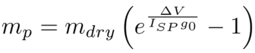
Apply a residual margin of 2 per cent (ESA regulation) to get the final propellant mass.
Hydrazine —
Density: 1.004 g/ml.
Melting point: 1.4oC.
Boiling point: 113.5oC.
Chemical formula: N2H4.
Molecular weight: 32.05.
Propellant pressure: 22bar.
Propellant storage temperature: 293K.
Propellant tank
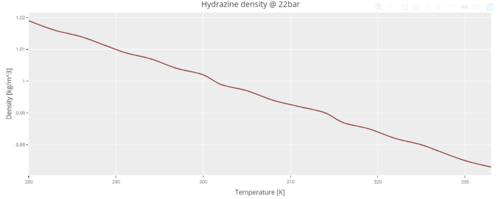
In order to size the propellant tanks, the above parameters have been considered. To determine the volume of propellant, it is necessary to calculate the density of hydrazine at the storage temperature. The density has been modelled as a dataset in Valispace (see below).

The volume of propellant can then be calculated with the following formula:
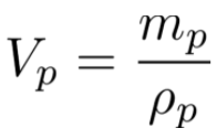
Ρp is the density of the propellant.
To obtain the internal volume of the tank, an ullage fraction must be taken into account (to prevent evaporation to cause an explosion). In this case, we consider the fraction to be 10 percent.
Using the formula of Volume of a cylinder with height being ¾ times the radius of the cylinder as an assumption, we can trace back to the value of the radius of the cylinder.
The thickness of the spherical tank can be calculated considering that the wall has to sustain the internal pressure. The minimum thickness assuring a surface tension equal to a certain limit tension value (related to the material and to a safety margin) is calculated with the formula:
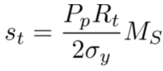
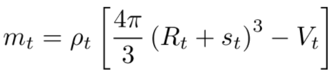
Considering that the yield stress for Titanium is 165 MN/m**2, and that the safety margin in aerospace is usually 2 , the thickness of the tanks can be computed. Hence, the mass of the tanks can be calculated as:
Pressurant tank
Pumping system, pressurant is used to pump the propellant out of the reservoir and to the combustion chamber. Moreover, it is usually necessary to have a fluid that could assure acceptable levels of pressure inside propellant tanks and the combustion chamber, as these get emptied while the mission proceeds. Their final pressure is the same as the propellant tanks (at the EoL). The normal pressure inside is 140 bar, which is eventually varied as per the requirements. The following parameters have been taken into account.
Number of tanks 2
Pressurant type helium
Pressurant initial pressure
Pressurant initial temperature
Tank material: Titanium
In order to calculate the initial mass of pressurant needed to fill the totality of the propellant volume, a conservation of energy approximation can be used:
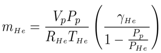
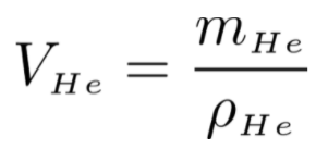
Where V_p and P_p are volume and pressure of the propellant, while T_He and P_He represent the pressurant initial values. Considering the data discussed in the previous sections, and considering that the gas constant and the heat capacity ratio for Helium, the initial mass of Helium in the pressurant tanks is calculated . Considering a density dataset at constant pressure, the volume of Helium is calculated using the following formula:
Here a margin on the volume is considered as usual, with an ullage fraction of 30 percent, the total tank volume is calculated. Starting with a value and repeating an analogous process to the one used in the propellant tank, it is possible to size the tanks. The minimum thickness required to sustain the internal pressure (taking into account a safety margin of 2 ) is calculated. This gives a mass of each tank and the total mass of Helium tanks.
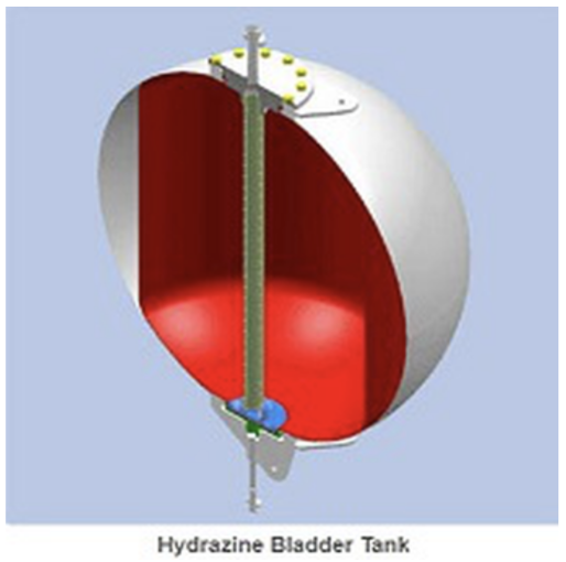
Process – Propellant is contained in the bladder and pressurant gas within the tank occupies the volume between the tank wall and bladder. The pressurant gas ‘squeezes’ the bladder forcing propellant through the stand-pipe to achieve a positive expulsion of propellant to a rocket engine or a set of thrusters. This process is controlled by the electronic pressure regulator which keep track of the low system pressure requirement and allow smaller quantities of propellants to smoothly flow through.
Flow control unit
FCU is another subsystem that is used to regulate the flow of propellant from the tanks to the combustion chamber. The selection principle here mainly depends on parameters like the inlet and outlet pressures which are indirectly dependent on the thruster requirements. Control valves are normally fitted with actuators and positioners which normally respond to signals generated by flow meters or temperature gauges.
Closed-Loop Control system uses the downstream temperature-corrected pressure measurement as a signal for closed-loop feedback, variable current is applied to the proportional flow control valve to control the effective flow restrictor inlet pressure and thereby control the mass flow rate to the thrusters.
FCU with Open Loop Control In this architecture, the flow rate control is performed using a feedback device outside the FCU, e.g. the thruster current. Based on the thruster current, variable current is applied to the proportional valve inside the FCU to control the flow rate.
With this, we come to the end phase of designing the basic subcomponents of a satellite propulsion system. We now leave you with this basic model which gives you the basic knowledge with which you can further build upon a complex iterative model which is as realistic as the working ones today. With Valispace, you can change any of these parameters that you designed in this stage one to aptly suit your requirements and approaches, create simulations and an analysis of the system overview and much more. It’s all yours to explore further.
Good luck and let us know how it goes!