In the last post we’ve left you with the thrust calculations but did you think about the condition Pe=Pa?
And that the thrust is maximum and the nozzle is said to be adapted?
This condition is called optimum or correct expansion. At high-temperature, flow is exhausted and it expands against the walls of the nozzle to create a force that pushes the vehicle forward.
When Pe is greater than Pa, the nozzle is under-extended which means the flow continues to expand outward after it has exited the nozzle and does not exert any force on the nozzle wall. When the opposite is true, it is over-extended and it causes the flow to squeeze back inward and separate from the walls of the nozzle. In both these cases, the efficiency of the system reduces.
Modelling the subcomponents using the calculated parameters
The right way of calculating thrust for a spacecraft in vacuum conditions of space is
T=m’*Ve+ Pa*Ae
and Pa = 1.01325 bars accurately.
Now, we will show you how those numbers influence the design of the major propulsion system subcomponents which are the following:
- Electronic pressure regulator;
- Flow control units;
- Thrusters;
- Propellants;
- Pressure valves;
- Propellant Tanks;
- Flow lines.
Electronic Pressure Regulator
Introduction
Satellites today utilize propellants to fuel the thrusters, for example, bipropellant propulsion systems with the fuel and oxidizer, which are expelled under constant pressure from the storage tank to the engine. Usage of electronic pressure regulators is the most commonly preferred method for precision attitude control. A small inner pressure sensor monitors the output pressure and a digital controller tweaks the timing of the valves to retain the required set-point.
The basic principle of the internal regulator system is that there exists a mechanical equilibrium between a spring force and a pressure force. The latter comes from the action of the outlet gas on a diaphragm. The pressure regulators are mainly composed of a poppet & seat, a power spring and a diaphragm. [1]
An electronic pressure regulator assembly allows the optimum pressure adjustment by minimizing propellant residuals by individual adaptation of pressures (mixture ratio for chemical propulsion) which enables lower complexity and minimizes spacecraft system mass and cost, to achieve optimum ISP for the mission phases. Xenon electronic pressure regulator is the most commonly preferred EPR.
Estimated Design Parameters
The system decreases the pressure from tank conditions (Propellant storage pressure – Hydrazine 22-27 bar – grade dependent) to an in-flight programmable set point (Chamber pressure 1-2 bar). In general, there are two different propulsion units fed:
1. The Electric Propulsion (EP) unit, with a minimum Xenon mass flow and;
2. The Cold Gas Thruster (CGT) unit, with a maximum Xenon mass flow.
Power consumption of the system is based on its mode of operation which is the product of the current and voltage ratings of the pressure regulator. Based on the above-defined parameters a perfectly suited electronic pressure regulator will be chosen such that it complements the thruster requirements.
Pressure cycle
Initially, the system undergoes a stage of xenon expansion where the pressure is reduced to approximately half the initial pressure proving PV = constant and keeping in mind the mass flow rate, has an added feed system to automatically balance its function. The second stage of pressure reduction follows the same principle and the pressure is further reduced to 2bar.
The feed system updates the completion of the cycle keeping in track of the mass flow rate of the working modes and helps the propellant flow systematically. This directly controls the propellant supply.
Thruster
Introduction
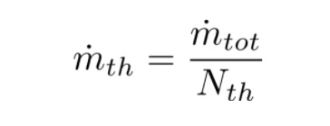
The Thruster design is based on the values of mass flow rate and thrust required by the spacecraft. Considering that one thruster alone cannot suffice all the thrust requirements also match the multidirectional thrust for various manoeuvres. We divide the mass flow rate value with the number of thrusters being mounted on the spacecraft.
In general, spacecrafts are mounted with two thrusters on the top and two on the bottom. This arrangement is purely mission-specific.
Iterative method
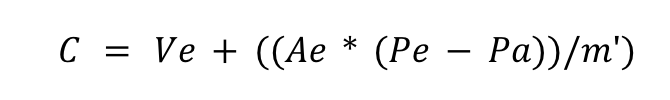
Effective exhaust velocity
It is rare that we are given the value of C directly, however, if the specific impulse for the rocket engine is given then we can easily calculate C. If in case the working and geometric variables of the Thruster are provided then we can use the below.
Characteristic Velocity
Characteristic exhaust velocity is the measure of energy available from the combustion process and is given by
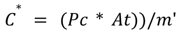
where Pc is the combustion chamber pressure and At is the area of the nozzle throat (discussed in the section below). Delivered values of C* range from about 1,333 m/s for monopropellant hydrazine up to about 2,360 m/s for cryogenic oxygen/hydrogen. [2]
We can now iterate those parameters that we previously calculated in part-1 using
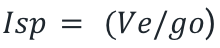
Exhaust Velocity:
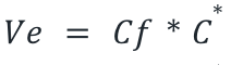
Specific Impulse:
Thruster Sizing
In this section, we’ll design the geometry of the thruster starting from the mass flow rate calculated in the previous section.
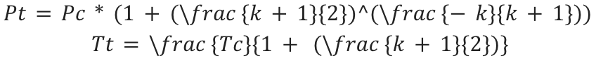
Pressure and Temperature at the nozzle throat (Pt & Tt)
These parameters are dependent on mainly the values of pressure and temperature inside the combustion chamber and specific heat ratio k,
The throat area is calculated by

Calculation of Mach number gives us the direct information of the nozzle exit area, the Mach number at the nozzle exit is given by the perfect gas expansion expression,
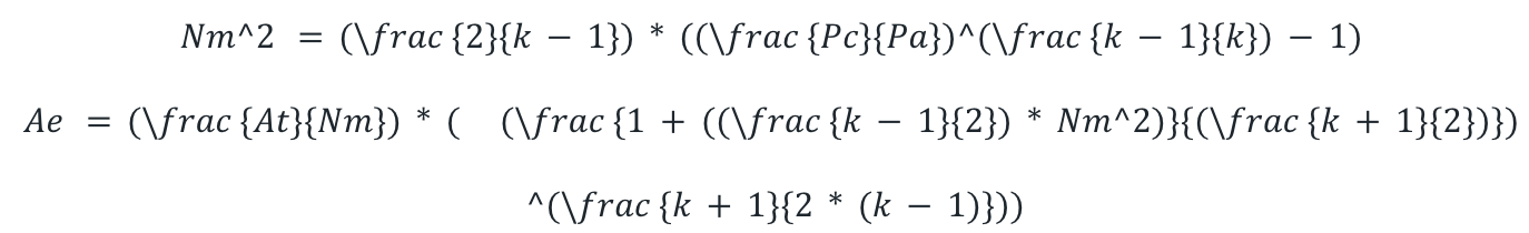
The section ratio, or expansion ratio, is defined as the area of the exit Ae divided by the area of the throat At.
Diameters of both the nozzle throat (Dt) and exit (De)can be calculated using
Design considerations for an optimum nozzle shape with a specific expansion ratio is that the gas flow at the nozzle exit must be uniform and axial for obtaining maximum momentum vector with minimum separation and negligible losses. Let us discuss about the Conical nozzle and bell nozzle.
Conical nozzle
The nozzle throat section shall form a circular arc with a radius ranging from 0.2 to 0.75 times the throat diameter. The half-angle of the nozzle convergent cone section ϴ can range from 20 to 45 degrees. The divergent cone half-angle α varies from approximately 12 to 18 degrees (15-degree standard is preferred). Certain performance losses occur in a conical nozzle as a result of the nonaxial component of the exhaust gas velocity, a correction factor λ is applied in the calculation of the exit-gas momentum.
First, the length of the convergent section Lconv computed considering a cone section with a convergent angle \theta of (Dch is the chamber diameter = Dc )
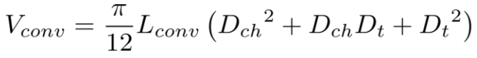
the volume of the Vconv convergent cone section is calculated with:
From this, it is possible to calculate the Vch volume of the combustion chamber using the following formula:
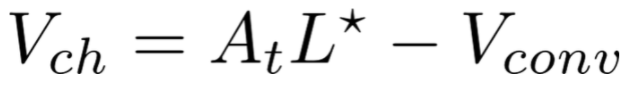
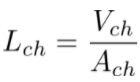
Where L^{\star} is the characteristic length, a parameter related to the combustion process. The chamber length is then calculated considering a cylindrical shape.
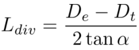
Finally, the divergent length can be computed by considering a cone section
The total length of the thruster is
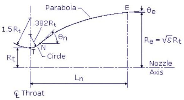
Bell nozzle
The figure and the name speak of how different it is from the conical nozzle. In terms of design parameter changes these are the major ones :
Half conical angle θn\theta n = 15 degrees
Arc radius upstream of the throat =1.5 Rt.
Arc radius of divergent section nozzle = 0.382 Rt Where Rt is the radius of the throat.
Part III is coming next week!
If you would like us to cover other space-related topics, feel free to reach out to engineering@valispace.com.
Thank you for reading.
References
1.Title – Fluidic simulations and tests of space mechanical pressure regulators: https://www.ecosimpro.com/wp-content/uploads/2015/02/SP2014_2969361_Lienart.pdf
2. http://www.braeunig.us/space/propuls.htm
3. Space Mission Analysis and Design (SMAD), 3rd Ed., James R. Wertz and Wiley J. Larson (1999)
4.SMALL GEO XENON PROPELLANT SUPPLY ASSEMBLY PRESSURE REGULATOR PANEL – Stefano Naclerio, Jesús Soto Salvador, Ernesto Such, Raúl Avezuela, Ramón Perez Vara (2012)
5.Development and Testing of EPR assembly – Erwin Freidl & Wolfgang Muller, Astrium GmbH (2000)
Image Source
https://lppfusion.com/science/space-propulsion/